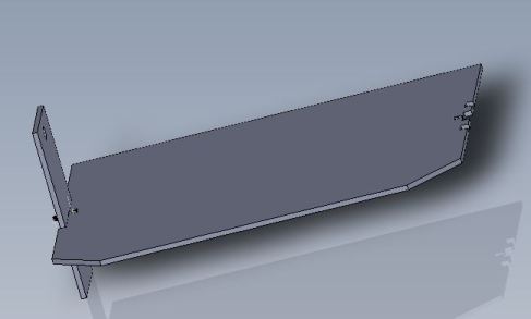
As a kid I was an avid fan of the battlebots TV show and when I first started hanging out at the GaTech Invention Studio, I was really excited to meet people who were actually building their own battle bots. After hanging out at a few battle bot competitions, I decided to attempt building my own. While building a battle bot had been on my to-do list for almost three years, I continually found it difficult to set aside enough time to actually design and build a robot that I could compete with. This year at DragonCon however, my buddies Xo Wang, Aaron Fan, and Mat Carroll told me I should build a robot for Motorama 2015 robot wars.

………fast forward to the weekend of February 6th 2015….

I waited until early February to actually begin working on my robot and this was an issue for several reasons:

  • battle bots take time to design and build (often quite a lot of time to build a very nice battle bot)
  • I was living in San Francisco where my only reasonably accessible machining resources were limited to 2 small consumer grade ABS 3D printers and a Roland MDX-40 CNC mill in the Google Garage
  • I was working at an internship that required me to work 40 hours a week (so I’d have to build the bot after work on weekdays)

Not fully realizing the challenges that were ahead and full of childlike excitement, I began designing my robot.

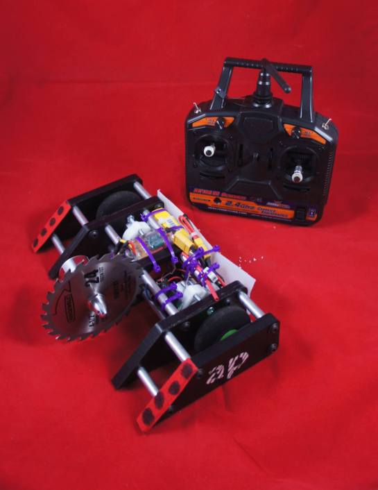
Due to my machining and time constraints, I decided to keep this robot as basic as possible using easy to machine materials and as many off-the-shelf components as possible. These design decisions led me to a beetle weight (3lb) vertical spinner robot which utilized a 4.5″ circular saw blade as its weapon and .5″ Ultra High Molecular Weight (UHMW) polyethylene sheet as the primary frame material. Since the design was inspired primarily by Charles Guan’s Nuclear Kitten IV robot, I settled on the name Atomic Puppy and began Computer Aided Drafting (CAD-ing) (logically I had to pick a name before CAD-ing so I knew what to base the design file names on).

Robo-CAD

I used the SolidWorks CAD program to design all of the robot parts that I would need to manufacture. This began with frame rails, and then the weapon and drive train components. To ease construction and maximize serviceability, I decided on a frame design that would be held together using 10mm outside diameter M6 threaded rods of varying lengths. From there on, it was basically a “plug and chug” operation. I measured my wheels, drive motors, and weapon components then designed a modular frame to fit all the components. By the end of Saturday night, I had all of my designs completed and my parts were ordered from McMaster Carr.

AtomicPuppyFinishedCAD

The finished CAD assembly of Atomic Puppy

Electronics

In keeping with the decision to use simple, off the shelf components, my electronics were as follows:

Manufacturing

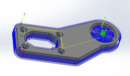
As mentioned above, I used the Google Garage for all of the parts manufacturing for this robot. Google may have a lot of perks, but my favorite by far is the Garage which is a little hacker space for Googlers (Google also has some really nice machine shops but those are limited to full time employees due to insurance reasons *infinite sadness*). Anyways, I coaxed my buddy Xo into showing me the in’s and outs of the Roland MDX-40 CNC router and began generating toolpaths for all of my parts using a CAM plug-in for SolidWorks called HSMworks. Once I had a few parts tool pathed, we spent the entire presidents day holiday determining optimal cut settings through a series of test cuts.

The tool-path for milling the weapon frame plate.

The tool-path for milling the weapon frame plate.

SIDE NOTE: UHMW is an awesome material but has some characteristics which make it particularly difficult to machine cleanly on the Computer Numerically Controlled (CNC) milling machine that I had access to. For instance, the Roland MDX-40 has a minimum spindle speed of 4500 rpms (which is incredibly high compared to most other CNC mills which typically go down to the 600’s for materials like stainless steel). Such a fast spindle speed means that while machining plastics (like for instance, UHMW), things are going to have a tendency to melt. To counteract the material’s inclination to melt, it is a good idea to pick an end mill with as few flutes as possible and cut at a fairly quick rate. The reasoning behind these two techniques is to essentially remove as much of the energy imparted into the material by the machine as possible through chips. Cutting fast with a small number of flutes and a slow spindle speed will typically be the easiest way to cut properly because large chips are formed and then are immediately cleared from the stock material so as not to heat the stock to the point of melting. If you’re able to cut UHMW without melting it, the resulting machined surfaces tend to be smooth and highly dimensionally tolerant. I settled on a spindle speed of 4500rpm, a cutting speed of 400mm/min, and used a 1/4″ diameter 2-flute end mill. Below is a short clip of machining with settings that aren’t quite right. You’ll notice a melty film forms along the edges of the cut and the chips are more like plastic powder, this is no bueno!

Making robot parts on the CNC mill in the Google Garage! #battlebot #google

A video posted by Chad Ramey (@charlesdramey) on Feb 16, 2015 at 8:56pm PST

After we had worked out the proper cut settings, it took about 3 days (about 6 hours after work each day) to mill out all of my frame components out of the UHMW sheets. Here is a quick clip with the proper settings in action. You’ll notice much less melting and substantially larger chips, now that is what I’m talking about!

Making robot parts on the CNC mill in the Google Garage! #battlebot #google

A video posted by Chad Ramey (@charlesdramey) on Feb 16, 2015 at 8:56pm PST

Since I was running very short on time (only a few days out from the competition), I for some reason decided that it would be a good idea to 3D print the hubs that would connect my 2.5″ diameter fly lite wheels to the drive motors (boy was I wrong!). I removed the stock ABS hubs from the wheels using brute force and ignorance, used calipers to measure the dimensions of the stock hubs, and then designed my own hubs which had a shaft collar on the end to allow the hub to connect securely to the drive motors. While I had no trouble actually printing the hubs on the Garage’s Up! Plus 2 printer, I discovered that the hubs weren’t entirely straight. When I test fit the hubs, they fit onto the motor shafts really well but, because they weren’t staright along their center axis they caused the wheels to rotate in a fashion that was highly cattywampus.

Assembly

Most of the assembly time was spent threading the 10mm OD 5.3mm ID aluminum rods with M6 threads through both ends. I spent one afternoon threading all 48 holes by hand (it wasn’t much fun). After all the rods were threaded, it was simply a matter of putting each rod between two frame rails and then bolting it in on both sides using a steel M6 screw. By the Friday morning (somewhere in the neighborhood of 3am) that we were scheduled to fly to the competition, I had the frame completely assembled with all the motors attached. Once we got to Harrisburg PA, I needed to finish the bot before the following day’s competition and was running on a full two hours of sleep so I decided it’d be a great idea to stay up all night and finish the assembly. It was at this point that I test drove the robot and realized just how terrible the 3D printed hubs were. After much consideration, I just decided to epoxy them onto the motor shafts in the straightest configuration possible. Fortunately my friend Gabe Ocha was around and he epoxied the wheels on while I finished soldering up the electronics. While the epoxy dried, I took a quick nap. The morning of the competition, I test drove the bot for the first time and was overwhelmingly happy that I’d actually had a completed bot to compete with.

Competition and Final Thoughts

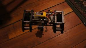
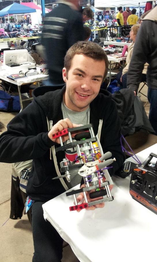
The completed Atomic Puppy robot!

The completed Atomic Puppy robot!

At the competition, I quickly discovered that the prop adapter I used for attaching the blade to the weapon motor was the Achilles heel of my robot. In both of my two matches I lost because when I hit the opponent with my blade spinning at full speed (~10k rpms), the prop adapter would just pop off and I would loose my weapon. For example, I lost my first match because during the first hit I got on the other robot, my blade went flying and I was left defenseless. Fortunately in my second match I was able to do some damage to the other robot before my blade popped off but ultimately the damage I did wasn’t enough for the judges to declare me the winner and so after losing two matches, I was eliminated from the tournament.

Although I didn’t win any matches, I still consider the weekend a monumental success. First of all, my robot is going home in fully operational condition despite taking many hard hits during the competition. I’ll be able to make a few small upgrades and the bot will be ready for more battles! Second, I’m so happy to have gotten to become more familiar with the CNC milling workflow and the fact that I was able to construct the robot in a week amazes me. Finally, I got to spend the weekend traveling and competing with some of the greatest engineers I know (plus, there was even some snow drifting in a waffle house parking lot!) so, post-competition I am one happy dude.

10982161_10153137675016660_4841364943765065515_o

I’d like to thank all of my friends who encouraged me to finally build a robot and also those who took time out of their crazy busy schedules to help make a dream of mine a reality.

If you have any questions or comments feel free to send them my way!

-Chad
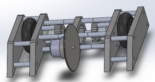
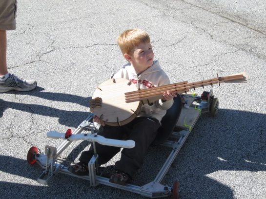
With a 12S LiPo battery pack, two 2.45 kW motors, and a brake pedal turned accelerator SouthernFried Chibi is a ton of fun that weighs in at around 30lbs thanks to its super light 8020 frame.

A small child enjoys the magnificence of southernfried chibi whilst wielding a wooden laser-cut banjo.

A small child enjoys the magnificence of southernfried chibi whilst wielding a wooden laser-cut banjo.

Project Background Info:

As I currently understand it, this go-kart started as Xo Wang’s (geekshavefeelings.com) mission to build a Charles Guan (www.etotheipiplusone.net/) inspired go-kart in a weekend’s time. Fortunately for me however, Xo ended up not  entirely finishing the kart and out of the goodness of his heart bestowed the project to me.

When I got the kart, it was a fame with wheels, steering, and some motors. Then began my construction efforts…

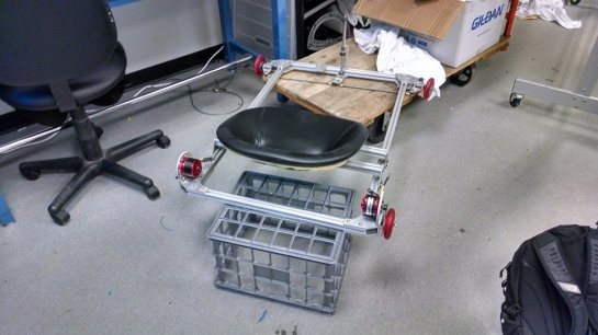
This is what the kart looked like when I got it

This is what the kart looked like when I got it

My Construction Efforts:

I quickly set about buying motor controllers and batteries for the cart. After much consideration I decided on:

While I was waiting for the electronics to arrive, I set about installing chains on the rear drive wheels. The chains utilized for this project were #25 size which is perfect for this power/torque range but makes things difficult when you need things like half links. Throughout the project I wasn’t able to find #25 chain parts anywhere locally which meant having to order chain parts from odd places in china and really long waits for new master links.

As soon as batteries and controllers were in my possession, I laser cut a .25″ thick acrylic electronics tray and went about attaching the controllers and batteries to it (you’ll notice however that the cart now utilizes a wooden tray because the acrylic tray broke D:). I also wired up two male-to-female banana plug jumpers which allow me to connect the 3 LiPo batteries in series. Finally some banana plug Y’s (to connect the batteries to both controllers) were soldered, some shorted pins (to turn the controllers on) were rigged together, and a 5K pot was wired in to both of the controller’s “throttle” leads and everything was ready to go!

All done! (I thought)

There was much rejoicing and lots of silly go-karting inside of MRDC!

You might notice in the video a loud clanking sound every time the cart accelerates. That clanking noise was the sound of chains not meshing properly with sprockets. Basically, the chains were skipping off of the sprockets #sadface.

Done forrealsies this time

After realizing I was going to need totally new sprockets for the rear wheels, I put off the kart for a long time. Instead of letting it sit around indefinitely however, I asked some awesome fellow University Lab Instructors from the GaTech Invention Studio to help me out. We all agreed on Atlanta Maker Faire for the new project deadline to force us to actually get the thing done.

Joshua and Kuttler putting some work into the kart!

Joshua and Kuttler putting some work into the kart!

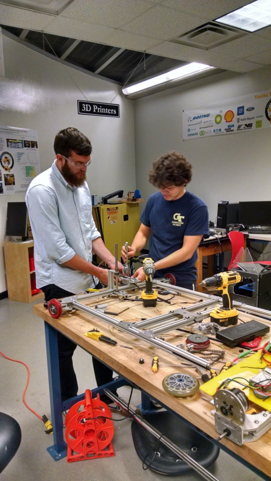
I brought in new scooter wheels and cut some better sprockets out using our waterjet. Joshua Terrell and Kuttler Smith brought a whole bunch of hard work and elbow grease. Joshua and Kuttler essentially rebuilt the entire cart. They remounted the seat to add more rigidity to the frame, made a woodern electronics tray, and a really nifty accelerator pedal. Xo originally made the pedal to be used for brakes but since we didn’t have brakes, Kutler rigged up a system of belts and springs so the pedal could be a “gas” pedal. I installed the new wheels and sprockets and the project was done!

If you have any questions, please feel free to leave them in the comments below.

Until next time,

Chad


Laser Cut Business Cards and Holder:
On Wednesday this week, Georgia Tech hosted the Atlanta MIT Business and Enterprise Forum: 3D Printing Startup Alley. I was was invited to set up a booth and represent the GaTech Invention at the event. Midday on Tuesday I realized I had no business cards for networking at the event so I set about fabricating some.

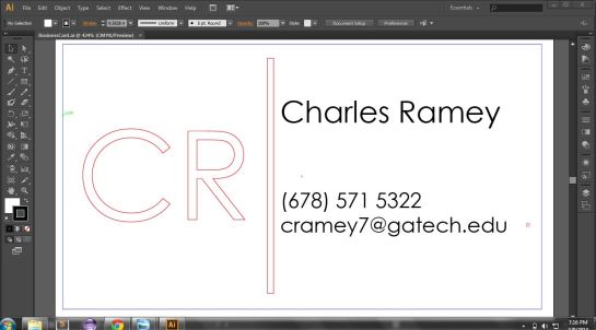
I began by designing the cards in Abode Illustrator:

Red lines are meant to be cut and black fonts are to be engraved.

Red lines are meant to be cut and black fonts are to be engraved.

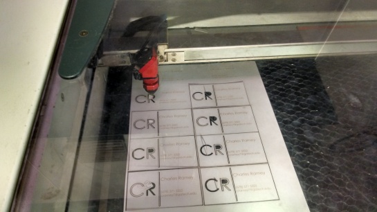
Then I loaded card stock into the laser engraver, set the correct power settings for cutting and engraving, focused the lens, and pressed go! On our Trotec 40 watt engraver, I used cut settings Power:60 Speed:40 and engrave settings of Power:15 Speed: 60.

Cutting the cards on our Trotec 40watt laser

Cutting the cards on our Trotec 40watt laser

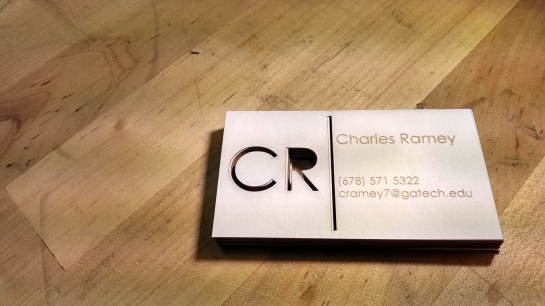
Although a bit flimsy, the finished cards came out much better than I expected.

Lasercut business cards made from cardstock.

Lasercut business cards made from cardstock.

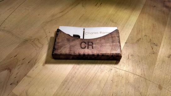
Finally, I used makercase (www.makercase.com/) to quickly design a card holder. I modified the makercase designs slightly using inkscape, loaded a 1mm thick plank of Black Walnut into the Trotec 40watt laser, and proceeded use the laser to cut the shapes out. After some assembly, gluing, and sanding the box came out to look like pretty great.

Black walnut card holder.

Black walnut card holder.

Guy Manuel Helmet:
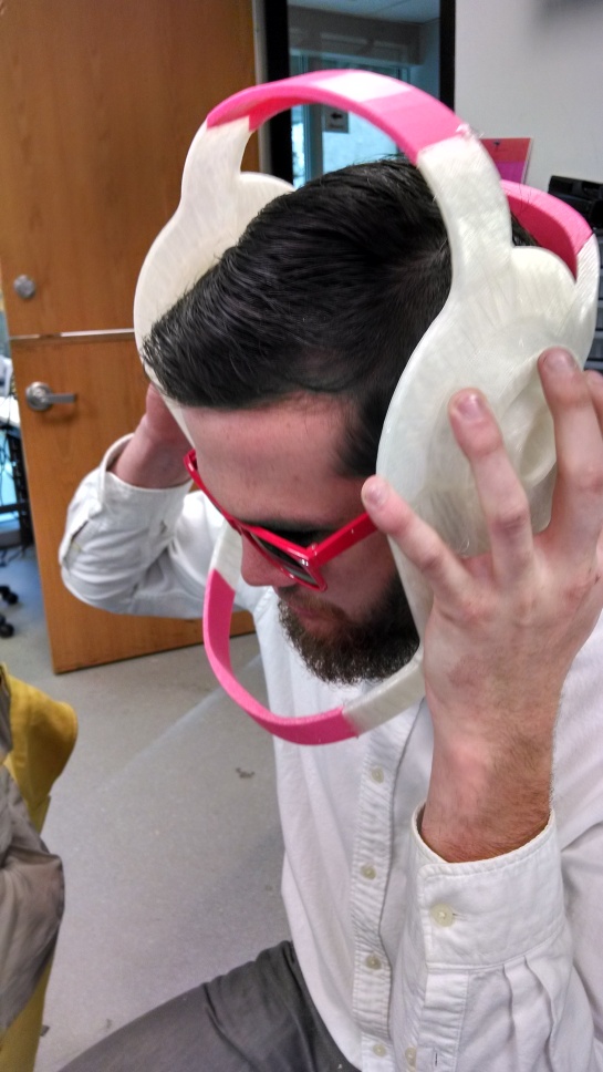
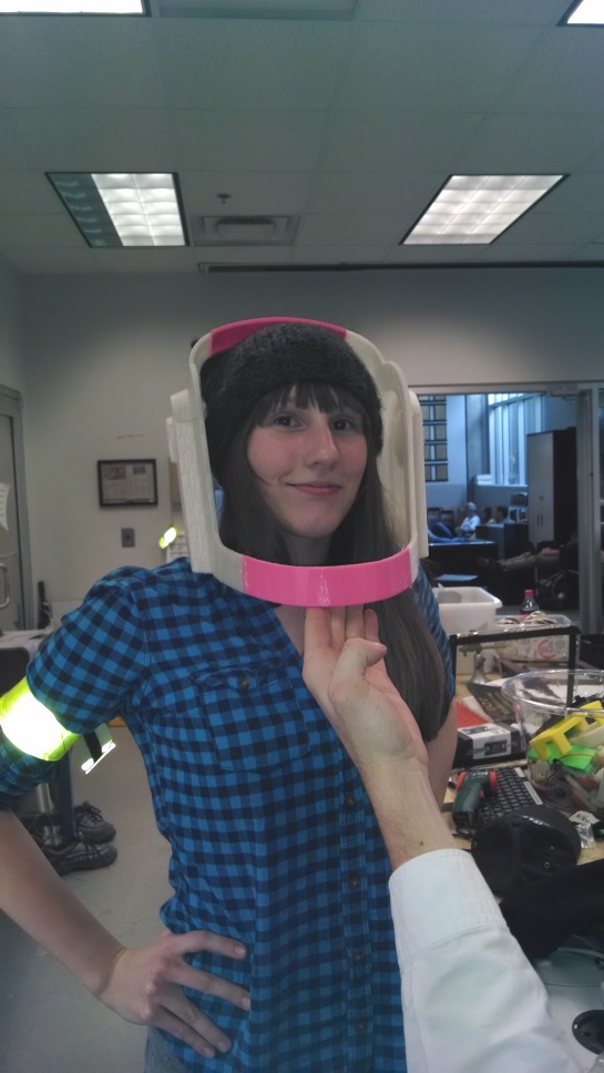
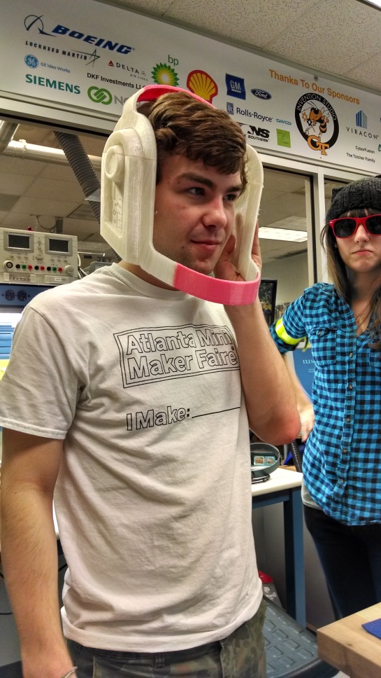
A friend and I are planning on going to DragonCon dressed as Daft Punk this year so naturally, we will require some custom made Daft Punk helmets. I am now on my third helmet prototype and I think this one will be the one I end up wearing around. I used Netfabb Basic to slice a SolidWorks design of the Guy-Manuel helmet up into 11 printable pieces. Over three days, I used the Invention Studio’s new Flash Forge Creator Printer to print all of the pieces. On Wednesday afternoon I glued all of the pieces together and took some test fit pictures. When I get some free time, I’ll post the design files on Thingiverse.

My friend Josh trying the helmet on.

My friend Josh trying the helmet on.


My friend Kara decided she wanted to try the helmet on as well.

My friend Kara decided she wanted to try the helmet on as well.


Kara looks cool with the red google sunglasses in the background.

Kara looks cool with the red google sunglasses in the background.

Gruyère, egg, and asparagus grilled cheese:
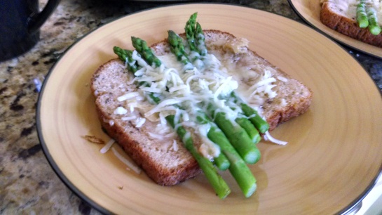
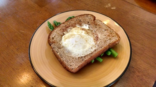
I had a bit of free time today so I decided to put my cooking skills to the test. Having recently learned about an awesome grilled cheese recipe, I went to publix and bought gruyere cheese, fresh asparagus, and 12 grain bread. I started by blanching the asparagus. Next I buttered all of the bread slices and grated the block of cheese. I then put cheese on four pieces of the bread and then laid about six pieces of asparagus on each piece ontop of the cheese. All of the pieces were placed onto the griddle until the cheese was melted. The last step was making four slices of “egg in a basket” (a fried egg inside of a piece of beard), on the griddle. Each of the egg in a basket pieces of bread were combined with a slice of asparagus and gruyere bread, plated, and then served. My family and I all really enjoyed them.

A slice of 12 grain toast with melted gruyere and asparagus

A slice of 12 grain toast with melted gruyere and asparagus


One of the four finished sandwiches.

One of the four finished sandwiches.

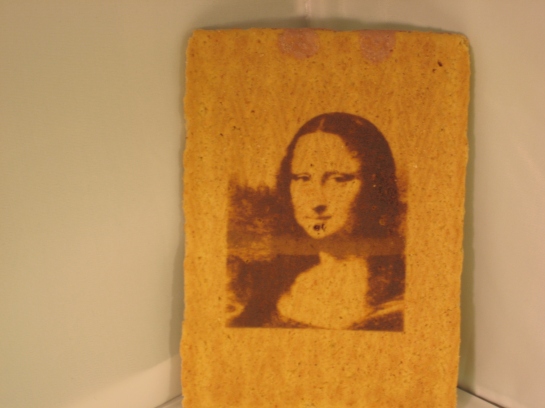
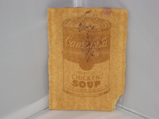
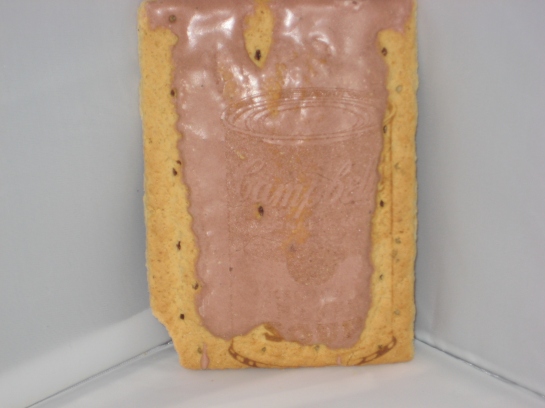
A few weeks ago, Snowpocalypse 2k14 hit Atlanta. Along with the snow came gratuitous amounts of free time so what other choice could I make than to laser engrave the Mona Lisa into some S’Mores PopTarts?!

I made use one of the three Trotec Laser Engravers at the Georgia Tech Invention Studio to do the deed. First, I downloaded the high-res image files from Google Images. Then the images were taken into GIMP where they were converted into lots of little black dots so they would play nice with the laser. For a technical description of this process, please reference Aaron Fan’s engraving with .

Finally, I used a test pop-tart (or rather a test-tart) to hone in the proper settings for engraving.

Here are a few of my first results:

S'Mores flavored Mona Lisa

S’Mores flavored Mona Lisa

Mona Lisa Back

Mmmmm tastes like .....S'Mores?

Mmmmm tastes like …..S’Mores?

Didn't engrave very well on the icing

Didn’t engrave very well on the icing

Expect more next time I have a bit of spare time. Any requests?

-Chad

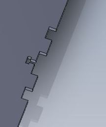
I finally had some time to sit down and finish the code for my DIY Segway or “ChadWay” as it has been named around the Invention Studio. This code is developed for an Arduino Uno and uses the servo library to send motor drive commands to a Sabertooth 2×25 motor controller.  I commented almost every line so it should be pretty easy to understand. If you have any questions, feel free to ask!

-Chad
#include <Servo.h> //includes the servo library in the code
#include <Wire.h>  //includes the servo library in the code 
#include <FreeSixIMU.h> //includes the servo library in the code
#include <FIMU_ADXL345.h> //includes the servo library in the code
#include <FIMU_ITG3200.h> //includes the servo library in the code
#define KP 0.5            // proportional controller gain
const int leftButtonPin = 2; //tells the arduino where the left steering button is
const int rightButtonPin = 3; //tells the arduino where the right steering button is 
int leftButtonState = 0; //creates a variable for the left switch's state to be stored to
int rightButtonState= 0; //creates a variables for the right switch's state to be stored to
Servo leftMotor;  //creates a servo instance for the left motor
Servo rightMotor; //creates a servo instance for the left motor 
float angles[3]; //creates an array for the sensor data to go in
FreeSixIMU sixDOF = FreeSixIMU();

void setup() 
{
  digitalWrite(10,LOW); //sets the pin to off
  digitalWrite(11,LOW); //sets the pin to off
  Serial.begin(9600);           // sets the serial BAUD rate
  delay(5); 
  sixDOF.init(); //initializes the sensor
  delay(5);
  pinMode(leftButtonPin, INPUT); //sets the port the button is plugged into as an input port
  pinMode(rightButtonPin, INPUT); //sets the port the button is plugged into as an input port
  Wire.begin(); //begins all the wire library stuff
  leftMotor.attach(10);          
  rightMotor.attach(11);          
  digitalWrite(10,LOW);  //sets the pin to off
  digitalWrite(11,LOW);  //sets the pin to off
}
void loop()
{
  float corrected_angles = 0.00;
  float output = 0.00;
  signed int motorL = 0;
  signed int motorR = 0;
  sixDOF.getEuler(angles); //Gets the angles array from the sensors
  corrected_angles=(angles[1]); //The angle component from the array
  corrected_angles=corrected_angles-3; //Adjusts the value to compensate for the sensor being mounted nonlevel
  output=corrected_angles*KP; //Proportional control loop
  output=output-.20; //Cleaning things up abit (a gain adjust)
  motorL=map(output,-30,30,150,30); //Maps sensor values to motor outputs
  motorR=map(output,-30,30,150,30); //Maps sensor values to motor outputs
  leftBuuttonState = digitalRead(leftButtonPin); //Reads the state of the left steering button
  rightButtonState = digitalRead(rightButtonPin); //Reads the state of the right steering button
  if(leftButtonState == HIGH) {   //If the state of the left steering button is high then tell motorL to go faster
    motorL=motorL+10;
  }
  if(rightButtonState == HIGH) {  //If the state of the left steering button is high then tell motorR to go faster
    motorR=motorR+10;
  }
  leftMotor.write(motorL);    //Writes speed value to the left motor
  rightMotor.write(motorR);   //Writes speed value to the right motor
}


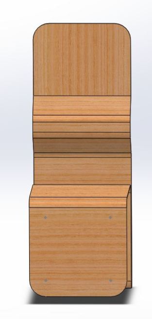
Today I discovered laser cut living hinges. For some reason the first thing I thought upon this discovery was “hmm.. this would make for an awesome chair. this awesome chair shall be called ‘das laser chair’.”

Anyways, if you have never seen or heard of living hinges (specifically the laser cut type) here are some of the links that got me started:

http://blog.makezine.com/2011/10/25/plywood-living-hinge-technique-for-laser-cutters/

On to das laser chair!

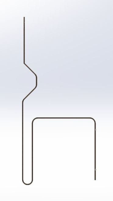
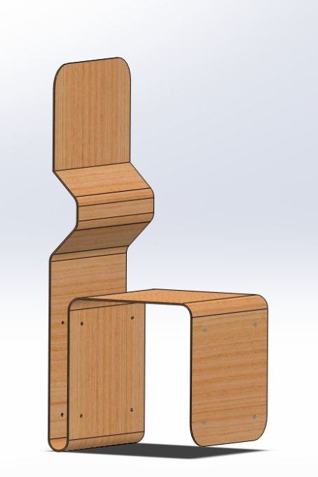
I whipped up this design in SolidWorks. The chair is still in progress; I need to smooth out the lumbar support, add the living hinges, and bolt the bottom legs together to hold everything together.

The living hinges will go where each of the bends are currently located.

ImageImageImage

As always, make sure to check back soon. I’ll keep you posted with any and all updates. Expect .dxf’s once I have the hinges in so you can make your own!

-Chad
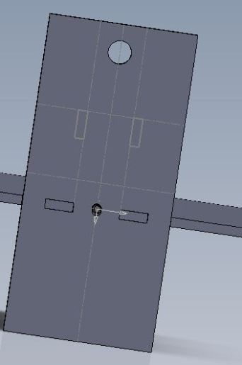
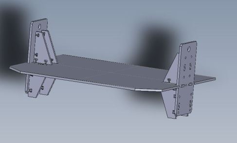
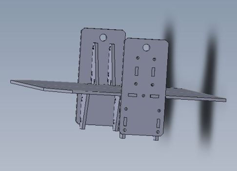
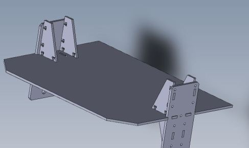
I have spent some more time in Solidworks working on the Chadway model. I am focusing on anchoring the wheel mounts so they won’t wobble or give in under the pressure of a rider on the platform. Each wheel mount has four braces attached to it plus an anchor point on the side of the platform.

Here are some pictures:

ImageImageImage